„Arduino modules” változatai közötti eltérés
| (52 közbenső módosítás, amit 2 másik szerkesztő végzett, nincs mutatva) | |||
| 2. sor: | 2. sor: | ||
<!--<categorytree mode=pages>Edu</categorytree> --> | <!--<categorytree mode=pages>Edu</categorytree> --> | ||
<categorytree mode=all style="float:right; clear:right; margin-left:1ex; border:1px solid gray; padding:0.7ex; background-color:white;">Edu</categorytree> | <categorytree mode=all style="float:right; clear:right; margin-left:1ex; border:1px solid gray; padding:0.7ex; background-color:white;">Edu</categorytree> | ||
==HC-SR04== | ==HC-SR04== | ||
{| class="wikitable" style="width: 900px; | {| class="wikitable" style="width: 900px; | ||
| 128. sor: | 128. sor: | ||
| Talaj nedvesség érzékelő | | Talaj nedvesség érzékelő | ||
| | | | ||
AO | AO | ||
DO | |||
GND | |||
VCC | |||
| 3.3V - 5 V | | 3.3V - 5 V | ||
| [[Fájl:3_Hygrometer.jpg|100x100px|bélyegkép|3_Hygrometer.jpg]] | | [[Fájl:3_Hygrometer.jpg|100x100px|bélyegkép|3_Hygrometer.jpg]] | ||
| 207. sor: | 207. sor: | ||
Részletek: | Részletek: | ||
<div class="mw-collapsible-content"> | <div class="mw-collapsible-content"> | ||
[[Fájl:4_mic.jpg |100x100px|bélyegkép|4_mic.jpg ]] | {| | ||
[[Fájl:4_mic2.jpg |100x100px|bélyegkép|4_mic2.jpg ]] | |- | ||
[[Fájl:4_mic3.jpg|100x100px|bélyegkép|4_mic3.jpg]] | |[[Fájl:4_mic.jpg |100x100px|bélyegkép|4_mic.jpg ]] | ||
|[[Fájl:4_mic2.jpg |100x100px|bélyegkép|4_mic2.jpg ]] | |||
|[[Fájl:4_mic3.jpg|100x100px|bélyegkép|4_mic3.jpg]] | |||
|} | |||
[http://www.waveshare.com/wiki/Sound_Sensor waveshare.com] | |||
| 312. sor: | 316. sor: | ||
|} | |} | ||
== Thermal Sensor == | == Temp Thermal Sensor == | ||
{| class="wikitable" style="width: 900px; | {| class="wikitable" style="width: 900px; | ||
| 337. sor: | 341. sor: | ||
| [[Fájl:7_thermo2.jpg|100x100px|bélyegkép]] | | [[Fájl:7_thermo2.jpg|100x100px|bélyegkép]] | ||
| style="text-align:right;"| 220 | | style="text-align:right;"| 220 | ||
| link | [http://ebay.to/2ouqt9V link] | | link | [http://ebay.to/2ouqt9V link]<br> [http://www.sunrom.com/p/temperature-sensor-module-ntc sunrom.com] | ||
|- | |- | ||
| 723. sor: | 728. sor: | ||
| | | | ||
VCC | VCC | ||
OUT | DO-OUT | ||
GND | GND | ||
| 4.5V - 20V | | 4.5V - 20V | ||
| 793. sor: | 798. sor: | ||
| style="text-align:right;"| 350 | | style="text-align:right;"| 350 | ||
| link | [http://ebay.to/2pNJacs link] | | link | [http://ebay.to/2pNJacs link] | ||
| link | [https://learn.sparkfun.com/tutorials/adxl345-hookup-guide tutorial] | | link | | ||
[https://learn.sparkfun.com/tutorials/adxl345-hookup-guide tutorial] | |||
[https://learn.adafruit.com/adxl345-digital-accelerometer/overview adafruit] | |||
|- | |- | ||
| 831. sor: | 838. sor: | ||
| | | | ||
VCC | VCC | ||
OUT | DO-OUT | ||
GND | GND | ||
| 5V | | 5V | ||
| 850. sor: | 857. sor: | ||
Working voltage :5 V<br> | Working voltage :5 V<br> | ||
Size: 28x12x8mm <br> | Size: 28x12x8mm <br> | ||
http://www.instructables.com/id/How-to-interface-Humidity-and-Temperature-DTH11-Se/ | |||
</div> | </div> | ||
</div> | </div> | ||
| 929. sor: | 939. sor: | ||
| Mágneses mező érzékelő | | Mágneses mező érzékelő | ||
| | | | ||
VCC | |||
DO-OUT | |||
GND | GND | ||
| 3.3V - 5V | | 3.3V - 5V | ||
| [[Fájl: 21_hall_switch_sensor.jpg |100x100px|bélyegkép| 21_hall_switch_sensor.jpg ]] | | [[Fájl: 21_hall_switch_sensor.jpg |100x100px|bélyegkép| 21_hall_switch_sensor.jpg ]] | ||
| 947. sor: | 957. sor: | ||
4, signal detection sensitivity can adjust <br /> | 4, signal detection sensitivity can adjust <br /> | ||
5, reserve all the way more circuits (P3 voltage drawn) <br /> | 5, reserve all the way more circuits (P3 voltage drawn) <br /> | ||
6, PCB board size: 30 (mm) x15 (mm)<br /> | 6, PCB board size: 30 (mm) x15 (mm)<br />[http://www.waveshare.com/wiki/Hall_Sensor waveshare.com] | ||
http://www.instructables.com/id/How-to-Measure-AC-Current-using-Hall-Effect-Sensor/ | |||
</div> | </div> | ||
</div> | </div> | ||
|} | |||
== HC-05 Bluetooth RF Transceiver Serial RS232 == | |||
{| class="wikitable" style="width: 900px; | |||
! nr | |||
! Modul | |||
! Típus | |||
! Csatlakozó | |||
! VCC | |||
! Kép | |||
! style="text-align:right;"| Ár/HUF | |||
! link | |||
! tutorial | |||
|- | |||
| nr | 20 | |||
| HC-05 Bluetooth | |||
| HC-05 Bluetooth | |||
| - State<br>- Rx <br>- Tx<br>- GND<br> - VCC <br>- EN | |||
| 3.3V - 6V működés <br> | |||
| [[Fájl: HC-05_bluetooth.jpg |100x100px|bélyegkép ]] | |||
| style="text-align:right;"| 640 | |||
| link | [http://ebay.to/2qUCyXR link] | |||
| turorial | [https://tronixlabs.com.au/news/tutorial-using-hc06-bluetooth-to-serial-wireless-uart-adaptors-with-arduino/ tronixstuff] | |||
[http://web.archive.org/web/20170316221520/https://tronixlabs.com.au/news/tutorial-using-hc06-bluetooth-to-serial-wireless-uart-adaptors-with-arduino/ webarchive] | |||
|- | |||
|colspan="9"| | |||
<div class="toccolours mw-collapsible mw-collapsed"> | |||
Részletek: | |||
<div class="mw-collapsible-content"> | |||
{| class="wikitable" | |||
|- | |||
| [[Fájl: HC-05_bluetooth2.jpg |100x100px|bélyegkép ]] | |||
| [[Fájl: HC-05_bluetooth3.jpg |100x100px|bélyegkép ]] | |||
| [[Fájl: HC-05_bluetooth4.jpg |100x100px|bélyegkép ]] | |||
|} | |||
</div> | |||
</div> | |||
|} | |} | ||
| 1 084. sor: | 1 138. sor: | ||
| [[Fájl: 23_ss49_1.jpg |100x100px|bélyegkép ]] | | [[Fájl: 23_ss49_1.jpg |100x100px|bélyegkép ]] | ||
| style="text-align:right;"| 290 | | style="text-align:right;"| 290 | ||
| | | | ||
[http://www.sunrom.com/p/ss49e-hall-sensor-linear-analog link] | |||
<br>[http://www.tme.eu/hu/details/ss49e/hall-erzekelok/honeywell/ TME] | |||
|- | |- | ||
| 1 093. sor: | 1 149. sor: | ||
[[Fájl:23_ss49_2.jpg|100x100px|bélyegkép]] | [[Fájl:23_ss49_2.jpg|100x100px|bélyegkép]] | ||
[[Fájl:23 ss49 3.jpg|100x100px|bélyegkép|23_ss49_3.jpg]] | [[Fájl:23 ss49 3.jpg|100x100px|bélyegkép|23_ss49_3.jpg]] | ||
Gyártó HONEYWELL <br> | |||
Az érzékelő típusa Hall <br> | |||
Érzékelő típusa bipoláris <br> | |||
Mérési tartomány 650...1000Gs <br> | |||
Tápfeszültség 3...6.5V DC <br> | |||
Átkapcsolási áram 6mA <br> | |||
Üzemi hőmérséklet -40...100°C<br> | |||
<br> | |||
[http://www.tme.eu/hu/Document/30447c50e7b2c9690d917bb3f82c99fe/ss49e-ss59et.pdf Dokumentáció] | |||
| 1 124. sor: | 1 189. sor: | ||
| style="text-align:right;"| 290 - 465FT | | style="text-align:right;"| 290 - 465FT | ||
| | | | ||
[http://ebay.to/2oW7Mi0 ebay | [http://ebay.to/2oW7Mi0 ebay 130Ft]<br> | ||
[http://www.sunrom.com/p/lm35-temperature-sensor-analog-out link]<br> | [http://www.sunrom.com/p/lm35-temperature-sensor-analog-out link]<br> | ||
[http://www.tme.eu/hu/details/lm35dz_nopb/homerseklet-jelatalakitok/texas-instruments/ TME]<br> | [http://www.tme.eu/hu/details/lm35dz_nopb/homerseklet-jelatalakitok/texas-instruments/ TME]<br> | ||
| 1 131. sor: | 1 196. sor: | ||
[https://learn.adafruit.com/tmp36-temperature-sensor Adafruit]<br> | [https://learn.adafruit.com/tmp36-temperature-sensor Adafruit]<br> | ||
[https://create.arduino.cc/projecthub/TheGadgetBoy/making-lcd-thermometer-with-arduino-and-lm35-36-c058f0 TheGadgetBoy]<br> | [https://create.arduino.cc/projecthub/TheGadgetBoy/making-lcd-thermometer-with-arduino-and-lm35-36-c058f0 TheGadgetBoy]<br> | ||
[https://blog.arduino.cc/2010/03/01/lm35-to-sense-negative-temperature/ negative temp]<br> | |||
| 1 299. sor: | 1 364. sor: | ||
|} | |} | ||
== NTC PTC thermistor == | |||
{| class="wikitable" style="width: 900px; | |||
! nr | |||
! Modul | |||
! Típus | |||
! Csatlakozó | |||
! VCC | |||
! Kép | |||
! style="text-align:right;"| Ár/HUF | |||
! link | |||
! tutorial | |||
|- | |||
| nr | 27 | |||
| Analog Temperature Sensor | |||
| VISHAY NTCLE100E3103JB0 <br> | |||
NTC termisztor; 10kΩ; <br> | |||
THT; 3977K; -40÷125°C; 500mW | |||
| | |||
AO | |||
VCC | |||
GND | |||
| 5V | |||
| [[Fájl: 27_thermo_NTC_3.jpg |100x100px|bélyegkép ]] | |||
| style="text-align:right;"| | |||
170 Ft(TME) | |||
| [http://www.tme.eu/hu/details/640-10k/tht-ntc-merotermisztorok/vishay/ntcle100e3103jb0/ TME] | |||
| [http://www.instructables.com/id/Temperatura-con-Termistor-NTC-10k-y-Arduino/ instructables.com] | |||
|- | |||
|colspan="9"| | |||
<div class="toccolours mw-collapsible mw-collapsed"> | |||
Részletek: | |||
<div class="mw-collapsible-content"> | |||
{| | |||
| [[Fájl:7 thermo NTC 1.jpg|100x100px|bélyegkép|7_thermo_NTC_1.jpg]] | |||
| [[Fájl:27 thermo NTC 2.jpg|100x100px|bélyegkép|27_thermo_NTC_2.jpg]] | |||
| [[Fájl:27 thermo NTC 4.jpg|100x100px|bélyegkép]] | |||
|} | |||
<p>There is a known non-linear relationship between the measured temperature and the NTC resistance value which exhibits, then measure the resistance value of the NTC temperature value can also be calculated in the measurement. Relationship between the resistance value of the NTC temperature values are as follows: | |||
</p> | |||
<pre>Rt = R x e^[B x (1/T1-1/T2)] | |||
</pre> | |||
<p>Where, Rt is thermistor resistance at temperature T1; R is the thermistor at room temperature T2 nominal resistance value; B value is an important parameter thermistor; T1 and T2 refers to the degree that is K Kelvin temperature, K degrees = 273.15 (absolute temperature) degrees Celsius.<br /> | |||
</p><p>Calculated inverse relationship between thermistor temperature and resistance value are as follows:<br /> | |||
</p> | |||
<pre>T1=1/(ln(Rt/R) /B 1/T2 ) | |||
</pre> | |||
<p>Measure the resistance values are generally known to use a series resistor values and applying a voltage of known size, measured by dividing the value of the known resistance of the resistor, to calculate the measured resistance is obtained, as shown in Figure 3. Facilities plus excitation voltage Eb, the thermistor resistance is Rt, the series resistor is Rs, then dividing the value series resistor: | |||
</p> | |||
<pre>Eout = Eb x Rs/(Rt Rs) | |||
</pre> | |||
<p>In addition to the series measurement, there is a Wheatstone bridge measurement method, shown in Figure 4. Let bridge excitation voltage Eb, the thermistor resistance is Rt, the bridge resistor as R1, R2 and R3, the bridge output voltage is: | |||
</p> | |||
<pre>out = Eb x R3/(Rt R3) – Eb x R2/(R1 R2) = Eb x [R3/(Rt R3) – R2/(R1 R2)] | |||
</pre> | |||
source http://www.electrodragon.com/w/index.php?title=Thermistor | |||
</div> | |||
</div> | |||
|} | |||
== VISHAY TSOP34838 IR Receiver == | |||
{| class="wikitable" style="width: 900px; | |||
! nr | |||
! Modul | |||
! Típus | |||
! Csatlakozó | |||
! VCC | |||
! Kép | |||
! style="text-align:right;"| Ár/HUF | |||
! link | |||
! tutorial | |||
|- | |||
| nr | 28 | |||
| IR sensor receiver | |||
| VISHAY TSOP34838 | |||
| | |||
GPIO | |||
VCC | |||
GND | |||
| 0.3 - 6V | |||
| [[Fájl: 2_IR_sensor.jpg |100x100px|bélyegkép ]] | |||
| style="text-align:right;"| | |||
200 Ft(TME) | |||
| [http://www.tme.eu/hu/details/tsop34838/ir-vevo-modulok/vishay/ TME] | |||
[https://www.adafruit.com/product/157 Adafruit] | |||
| [https://learn.adafruit.com/ir-sensor/overview Adafruit] | |||
|} | |||
== IR adó - 5mm - 940nm == | |||
{| class="wikitable" style="width: 900px; | |||
! nr | |||
! Modul | |||
! Típus | |||
! Csatlakozó | |||
! VCC | |||
! Kép | |||
! style="text-align:right;"| Ár/HUF | |||
! link | |||
! tutorial | |||
|- | |||
| nr | 29 | |||
| LUCKY LIGHT LL-503IRT2E-2AC | |||
| IR adó; 5mm; 940nm | |||
| | |||
GPIO | |||
VCC | |||
GND | |||
| 0.3 - 6V | |||
| [[Fájl: 2_IR_ado.jpg |100x100px|bélyegkép ]] | |||
| style="text-align:right;"| | |||
20 Ft(TME) | |||
| [http://www.tme.eu/hu/details/ll-503irt2e-2ac/ir-led-ek/lucky-light/ TME] | |||
| [https://learn.adafruit.com/ir-sensor/making-an-intervalometer Adafruit] | |||
|} | |||
== Phototransistor == | |||
http://learn.parallax.com/tutorials/robot/shield-bot/robotics-board-education-shield-arduino/chapter-6-light-sensitive-14 | |||
== LED as light sensor == | |||
http://makezine.com/projects/make-36-boards/how-to-use-leds-to-detect-light/ | |||
http://www.instructables.com/id/LEDs-as-light-sensors/ | |||
http://www.thebox.myzen.co.uk/Workshop/LED_Sensing.html | |||
https://web.archive.org/web/20170506225716/http://www.thebox.myzen.co.uk/Workshop/LED_Sensing.html | |||
http://web.archive.org/web/20170211022102/http://makezine.com/projects/make-36-boards/how-to-use-leds-to-detect-light/ | |||
== Linkek == | |||
https://www.adafruit.com/category/35 | |||
https://tkkrlab.nl/wiki/Arduino_37_sensors | |||
http://www.waveshare.com/wiki/Main_Page#Sensors | |||
[https://www.adafruit.com/product/176 Adafruit sensor pack] | |||
[https://www.youtube.com/watch?v=v4BbSzJ-hz4 encoder explained video ] | |||
A lap jelenlegi, 2017. július 28., 16:47-kori változata
HC-SR04
| nr | Modul | Típus | Csatlakozó | VCC | Kép | Ár/HUF | link | tutorial |
|---|---|---|---|---|---|---|---|---|
| 1 | HC-SR04 | ultrahang távolságmérő |
VCC TRIG ECHO GND |
5V | 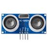 |
330 | link | tutorial |
|
Részletek: Working Voltage : 5V(DC)
| ||||||||
IR Infrared Obstacle Avoidance Sensor
| nr | Modul | Típus | Csatlakozó | VCC | Kép | Ár/HUF | link | tutorial
|
|---|---|---|---|---|---|---|---|---|
| 2 | IR | Infra akadály érzékelő |
DO GND VCC |
3.3V - 5V |  |
220 | link | tutorial |
|
Részletek: 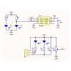 Features: When the module detects obstacles in front of the signal, the circuit board green indicator light level, while the OUT port continuous output low-level signals, the module detects a distance of 2 ~ 80cm, detection angle 35 °, the detection distance can be potential adjustment with adjustment potentiometer clockwise, the increase in detection distance; counterclockwise adjustment potentiometer, the detection distance decreased. the sensor active infrared reflection detection, target reflectivity and shape of the detection distance of the key. The black minimum detection range, white maximum; small area object distance is small, a large area from the large. The sensor module output port OUT can be directly connected with the microcontroller IO port can also be driven directly to a 5V relay; Connection: VCC-VCC; GND-GND; OUT-IO | ||||||||
Hygrometer
| nr | Modul | Típus | Csatlakozó | VCC | Kép | Ár/HUF | link | tutorial |
|---|---|---|---|---|---|---|---|---|
| 3 | Hygrometer | Talaj nedvesség érzékelő |
AO DO GND VCC |
3.3V - 5 V | 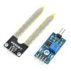 |
220 | link | analog read |
|
Részletek: 1. This is a simple water sensor can be used to detect soil moisture when the soil moisture deficit module outputs a high level, and vice versa output low. Use this sensor produced an automatic plant waterer device, so that the plants in your garden without people to manage. | ||||||||
Mikrofon
| nr | Modul | Típus | Csatlakozó | VCC | Kép | Ár/HUF | link | tutorial |
|---|---|---|---|---|---|---|---|---|
| 4 | Mikrofon | Hang | 3 PIN verzió VCC GND DO 4 PIN verzió DO VCC GND AO |
3 PIN verzió 3.3V-5V 4 PIN verzió |
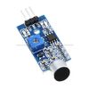 |
220 | link |
tutorial |
|
Részletek: | ||||||||
Digitális légköri nyomás
| nr | Modul | Típus | Csatlakozó | VCC | Kép | Ár/HUF | link | tutorial |
|---|---|---|---|---|---|---|---|---|
| 5 | Digitális légköri nyomás | Nyomás | I2C VCC GND SCL SDA |
1.8V - 3.6V |  |
220 | link | |
|
Részletek 1.8V to 3.6V Supply Voltage | ||||||||
Fotóellenállás
| nr | Modul | Típus | Csatlakozó | VCC | Kép | Ár/HUF | link | tutorial |
|---|---|---|---|---|---|---|---|---|
| 6 | Fotóellenállás | Fény |
AO DO GND VCC |
3.3V - 5V |
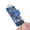 |
220 | link | |
|
Részletek Using sensitive photosensitive resistance sensor | ||||||||
Temp Thermal Sensor
| nr | Modul | Típus | Csatlakozó | VCC | Kép | Ár/HUF | link | tutorial |
|---|---|---|---|---|---|---|---|---|
| 7 | Thermal Sensor | Hőérzékelő | 3.3V - 5V |
AO DO GND VCC |
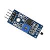 |
220 | link sunrom.com
| |
|
Részletek 1. Using the NTC thermistor sensor , good sensitivity | ||||||||
Digitális enkóder
| nr | Modul | Típus | Csatlakozó | VCC | Kép | Ár/HUF | link | tutorial
|
|---|---|---|---|---|---|---|---|---|
| 8 | Digitális enkóder | enkóder |
CLK DT SW VCC GND |
5V | 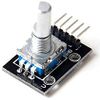 |
220 | link | |
|
Részletek Size: About 31 * 19 * 29mm / 1.22" * 0.75" * 1.14" | ||||||||
MQ-2 MQ2 Gas Sensor
| nr | Modul | Típus | Csatlakozó | VCC | Kép | Ár/HUF | link | tutorial |
|---|---|---|---|---|---|---|---|---|
| 9 | MQ-2 MQ2 Gas Sensor | Gáz Metán, Bután, füst érzékelő |
5V |
AO DO GND VCC |
 |
360 | link | |
|
Részletek: 1. size: 32mmX22mmX27mm | ||||||||
MQ-7 MQ7 Gas Sensor
| nr | Modul | Típus | Csatlakozó | VCC | Kép | Ár/HUF | link | tutorial |
|---|---|---|---|---|---|---|---|---|
| 10 | MQ-7 MQ7 Carbon Monoxide CO Gas Sensor | szénMonoxid érzékelő |
AO DO GND VCC |
5V | 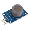 |
400 | link | |
|
Részletek: 1. With the signal output indicator; | ||||||||
SW-420 Motion Sensor
| nr | Modul | Típus | Csatlakozó | VCC | Kép | Ár/HUF | link | tutorial |
|---|---|---|---|---|---|---|---|---|
| 11 | SW-420 Motion Sensor | Mozgatás, remegés érzékelő |
DO GND VCC |
3.3V - 5V | 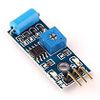 |
220 | link | |
|
Részletek: Used to trigger the effect of various vibration, theft alarm, intelligent car, earthquake alarm, motorcycle alarm, etc.
This module is compared with the normally open type vibration sensor module, vibration trigger for longer periods of time, can drive the relay module | ||||||||
Humidity and Rain Detection
| nr | Modul | Típus | Csatlakozó | VCC | Kép | Ár/HUF | link | tutorial |
|---|---|---|---|---|---|---|---|---|
| 12 | Humidity and Rain Detection | Nedvesség, eső |
AO DO GND VCC |
3.3V - 5V |  |
270 | link | |
|
Részletek: rain sensor, can be used for all kinds of weather monitoring, and translated into output signals and AO. | ||||||||
Speed Sensor Module
| nr | Modul | Típus | Csatlakozó | VCC | Kép | Ár/HUF | link | tutorial |
|---|---|---|---|---|---|---|---|---|
| 13 | Speed Sensor Module | Tachometer - fordulatszám mérő |
AO DO GND VCC |
3.3V - 5V |  |
290 | link | |
|
Részletek: Groove Width: 5mm | ||||||||
Infrared Flame Detection Sensor
| nr | Modul | Típus | Csatlakozó | VCC | Kép | Ár/HUF | link | tutorial |
|---|---|---|---|---|---|---|---|---|
| 14 | IR Infrared Flame Detection Sensor | infra fény, tűz |
AO DO GND VCC |
3.3V - 5v | 290 | link
| ||
|
Részletek: 1. can detect the flame or the wavelength at 760 nm to 1100 nm range of the light source, the test flame lighters distance of 80cm, the larger the flame, the greater the distance test | ||||||||
HC-SR501
| nr | Modul | Típus | Csatlakozó | VCC | Kép | Ár/HUF | link | tutorial |
|---|---|---|---|---|---|---|---|---|
| 15 | HC-SR501 | Infra mozgásérzékelő Pyroelectric Infrared Sensor |
VCC DO-OUT GND |
4.5V - 20V |  |
290 | link | |
|
Részletek: HC--SR501 Body Sensor Module | ||||||||
ADXL345 Accelerometer
| nr | Modul | Típus | Csatlakozó | VCC | Kép | Ár/HUF | link | tutorial
|
|---|---|---|---|---|---|---|---|---|
| 16 | ADXL345 Accelerometer | Gyroscope elfordulás érzékelő | I2C vagy SPI 2x interrupt Részletek: - GND |
3V-5V | 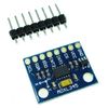 |
350 | link | |
|
Részletek: 1. Adxl345 digital three-axis acceleration of gravity tilt module arduino code iic / spi. | ||||||||
DHT11 Temperature and Humidity
| nr | Modul | Típus | Csatlakozó | VCC | Kép | Ár/HUF | link | tutorial |
|---|---|---|---|---|---|---|---|---|
| 17 | DHT11 Temperature and Humidity | Hő és nedvesség/pára |
VCC DO-OUT GND |
5V | 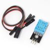 |
300 | link | |
|
Részletek: Specification: http://www.instructables.com/id/How-to-interface-Humidity-and-Temperature-DTH11-Se/ | ||||||||
RF 433MHz Transmitter/Receiver
| nr | Modul | Típus | Csatlakozó | VCC | Kép | Ár/HUF | link | tutorial |
|---|---|---|---|---|---|---|---|---|
| 18 | RF 433MHz Transmitter/Receiver | 433 rádió adó/vevő | -Data -Data - VCC - GND |
5V transmitter 3.5V-12V receiver |
 |
250 | link | |
|
Részletek: TX Technical Specifications: | ||||||||
Hall switch sensor
| nr | Modul | Típus | Csatlakozó | VCC | Kép | Ár/HUF | link | tutorial |
|---|---|---|---|---|---|---|---|---|
| 19 | Hall switch sensor | Mágneses mező érzékelő |
VCC DO-OUT GND |
3.3V - 5V | 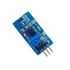 |
290 | link | |
|
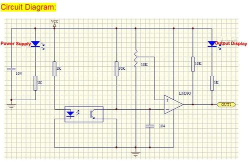
Részletek: 1, on-board LM393 voltage comparator chip and hall sensing probe http://www.instructables.com/id/How-to-Measure-AC-Current-using-Hall-Effect-Sensor/ | ||||||||
HC-05 Bluetooth RF Transceiver Serial RS232
| nr | Modul | Típus | Csatlakozó | VCC | Kép | Ár/HUF | link | tutorial |
|---|---|---|---|---|---|---|---|---|
| 20 | HC-05 Bluetooth | HC-05 Bluetooth | - State - Rx - Tx - GND - VCC - EN |
3.3V - 6V működés |
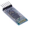 |
640 | link | tronixstuff |
DRV8825 motor driver
| nr | Modul | Típus | Csatlakozó | VCC | Kép | Ár/HUF | link | tutorial |
|---|---|---|---|---|---|---|---|---|
| 20 | DRV8825 motor driver | Léptető motor meghajtó | - ENABLE - STEP - DIR - RESET - VCC - GND |
3.3V - 5V működés 8.2 – 45 V - 1.5 A / fázis hűtés nélkül, hűtéssel 2.2 A |
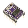 |
470 | link | |
|
Részletek: Features: The DRV8825 stepper motor driver carrier is a breakout board for TI's DRV8825 microstepping bipolar stepper motor driver. The module has a pinout and interface that are nearly identical to those of our A4988 stepper motor driver board, so it can be used as a higher-performance drop-in replacement for those boards in many applications. This product is a carrier board or breakout board for TI’s DRV8825 stepper motor driver; we therefore recommend careful reading of the DRV8825 datasheet (1MB pdf) before using this product. This stepper motor driver lets you control one bipolar stepper motor at up to 2.2 A output current per coil (see the Power Dissipation Considerations section below for more information). Here are some of the driver’s key features:
| ||||||||
Motor Drive Shield Expansion Board L293D Module
| nr | Modul | Típus | Csatlakozó | VCC | Kép | Ár/HUF | link | tutorial |
|---|---|---|---|---|---|---|---|---|
| 21 | Motor vezérlő | Motor vezérlő | - OUT - VCC - GND |
3.3V - 5V | 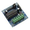 |
290 | link | |
|
Részletek: L293D motor shield, the input voltage DC4.5-25V | ||||||||
SS49E - Hall Sensor - Linear Analog
| nr | Modul | Típus | Csatlakozó | VCC | Kép | Ár/HUF | link | tutorial |
|---|---|---|---|---|---|---|---|---|
| 22 | Hall Sensor | Hall Sensor |
Analog OUT VCC GND |
3.3V - 5V | 
|
290 | ||
|
Részletek:   Gyártó HONEYWELL
| ||||||||
LM35 vagy TMP36GT9Z Temperature Sensor Analog OUT
| nr | Modul | Típus | Csatlakozó | VCC | Kép | Ár/HUF | link | tutorial |
|---|---|---|---|---|---|---|---|---|
| 23 | LM35 Temperature Sensor | LM35 Temperature Sensor |
Analog OUT VCC GND |
3.3V - 5V | 
|
290 - 465FT |
Adafruit
| |
|
Részletek:   Calibrated directly in Celsius (Centigrade)
| ||||||||
Vibration Sensor SW-18020P
| nr | Modul | Típus | Csatlakozó | VCC | Kép | Ár/HUF | link | tutorial |
|---|---|---|---|---|---|---|---|---|
| 24 | Vibration Sensor | Vibration Sensor |
Analog OUT VCC GND |
5V | 
|
290 | link | |
|
Részletek:
 Specifications Maximum working voltage (Vmax) : 12V | ||||||||
LDR 5mm - Light Dependent Resistor
| nr | Modul | Típus | Csatlakozó | VCC | Kép | Ár/HUF | link | tutorial |
|---|---|---|---|---|---|---|---|---|
| 25 | LDR | LDR |
Analog OUT (R) |
5V | 
|
220 | link
|
DS18B20
| nr | Modul | Típus | Csatlakozó | VCC | Kép | Ár/HUF | link | tutorial |
|---|---|---|---|---|---|---|---|---|
| 26 | Digital Temperature Sensor | Highly accurate and easy to interface |
DO VCC GND |
5V | 
|
290 Ft(ebay) |
linkTME | instructables.com |
|
Részletek: 1-Wire Digital Thermometer
| ||||||||
NTC PTC thermistor
| nr | Modul | Típus | Csatlakozó | VCC | Kép | Ár/HUF | link | tutorial | |||
|---|---|---|---|---|---|---|---|---|---|---|---|
| 27 | Analog Temperature Sensor | VISHAY NTCLE100E3103JB0 NTC termisztor; 10kΩ; |
AO VCC GND |
5V |
170 Ft(TME) |
TME | instructables.com | ||||
|
Részletek:
There is a known non-linear relationship between the measured temperature and the NTC resistance value which exhibits, then measure the resistance value of the NTC temperature value can also be calculated in the measurement. Relationship between the resistance value of the NTC temperature values are as follows: Rt = R x e^[B x (1/T1-1/T2)] Where, Rt is thermistor resistance at temperature T1; R is the thermistor at room temperature T2 nominal resistance value; B value is an important parameter thermistor; T1 and T2 refers to the degree that is K Kelvin temperature, K degrees = 273.15 (absolute temperature) degrees Celsius. Calculated inverse relationship between thermistor temperature and resistance value are as follows: T1=1/(ln(Rt/R) /B 1/T2 ) Measure the resistance values are generally known to use a series resistor values and applying a voltage of known size, measured by dividing the value of the known resistance of the resistor, to calculate the measured resistance is obtained, as shown in Figure 3. Facilities plus excitation voltage Eb, the thermistor resistance is Rt, the series resistor is Rs, then dividing the value series resistor: Eout = Eb x Rs/(Rt Rs) In addition to the series measurement, there is a Wheatstone bridge measurement method, shown in Figure 4. Let bridge excitation voltage Eb, the thermistor resistance is Rt, the bridge resistor as R1, R2 and R3, the bridge output voltage is: out = Eb x R3/(Rt R3) – Eb x R2/(R1 R2) = Eb x [R3/(Rt R3) – R2/(R1 R2)] source http://www.electrodragon.com/w/index.php?title=Thermistor
| |||||||||||
VISHAY TSOP34838 IR Receiver
| nr | Modul | Típus | Csatlakozó | VCC | Kép | Ár/HUF | link | tutorial |
|---|---|---|---|---|---|---|---|---|
| 28 | IR sensor receiver | VISHAY TSOP34838 |
GPIO VCC GND |
0.3 - 6V | 
|
200 Ft(TME) |
TME | Adafruit |
IR adó - 5mm - 940nm
| nr | Modul | Típus | Csatlakozó | VCC | Kép | Ár/HUF | link | tutorial |
|---|---|---|---|---|---|---|---|---|
| 29 | LUCKY LIGHT LL-503IRT2E-2AC | IR adó; 5mm; 940nm |
GPIO VCC GND |
0.3 - 6V | 
|
20 Ft(TME) |
TME | Adafruit |
Phototransistor
LED as light sensor
http://makezine.com/projects/make-36-boards/how-to-use-leds-to-detect-light/
http://www.instructables.com/id/LEDs-as-light-sensors/
http://www.thebox.myzen.co.uk/Workshop/LED_Sensing.html
https://web.archive.org/web/20170506225716/http://www.thebox.myzen.co.uk/Workshop/LED_Sensing.html
Linkek
https://www.adafruit.com/category/35
https://tkkrlab.nl/wiki/Arduino_37_sensors


